Diagram A Circuit That Employs The 2s-complement Negation Tr
Solved: a) design a four-bit 2's complement circuit with a control Solved march 23rd: (lecture #20) use two's complement wat s Question #01 a. explain if the circuit in figure 2 is
Solved Consider the two circuit diagrams below. These two | Chegg.com
Answered: consider the two circuit diagrams… Full adder and subtractor circuit diagram [diagram] 2 s complement logic diagram
Understanding two's complement
Solved design a circuit that computes the twos complement ofFigure 4 from an approach for realization of 2's complement adder Solved circuit iiTwo’s complement.
Fra221b6574: บทสรุปการเรียน week2Design a combinational circuit that produce 2’s complement of a 4-bit Verilog 2 complemento de complemento / surtraciónSolved circuit 2 figure 4. circuit 2 schematic circuit 2.
![[DIAGRAM] 2 S Complement Logic Diagram - MYDIAGRAM.ONLINE](https://i.ytimg.com/vi/CERP3HbUZRQ/maxresdefault.jpg)
Complement adder subtractor gate realization reversible dkg
Solved circuit below is a two's complement generator using jConsider the two circuit diagram below Complement binary two bit number subtraction twos integers figure represented negativeSolved 2) two circuit diagrams are given below. a given.
Solved here is a two's complement representation of anSolved design the following circuit for 2s complement Solved consider the two circuit diagrams below. these twoBinary subtraction with two's complement.

Figure 1 from design and implementation of high performance two’s
Complement twos binarySolved 1- draw the logic circuit diagram that implement the 2.13 draw logic diagram to implement the following boolean expressions[diagram] 2 s complement circuit diagram.
2's complement circuit. compared to a conventional adder 2's complementSolved combinational circuit for twos complementer [diagram] 2 s complement logic diagram[diagram] 2 s complement logic diagram.

[diagram] 2 s complement logic diagram
[solved]: problem 1: question consider the two circuit diaSolved schematic below represents a given circuit with two .
.


SOLVED: a) Design a four-bit 2's complement circuit with a control

Solved Here is a two's complement representation of an | Chegg.com
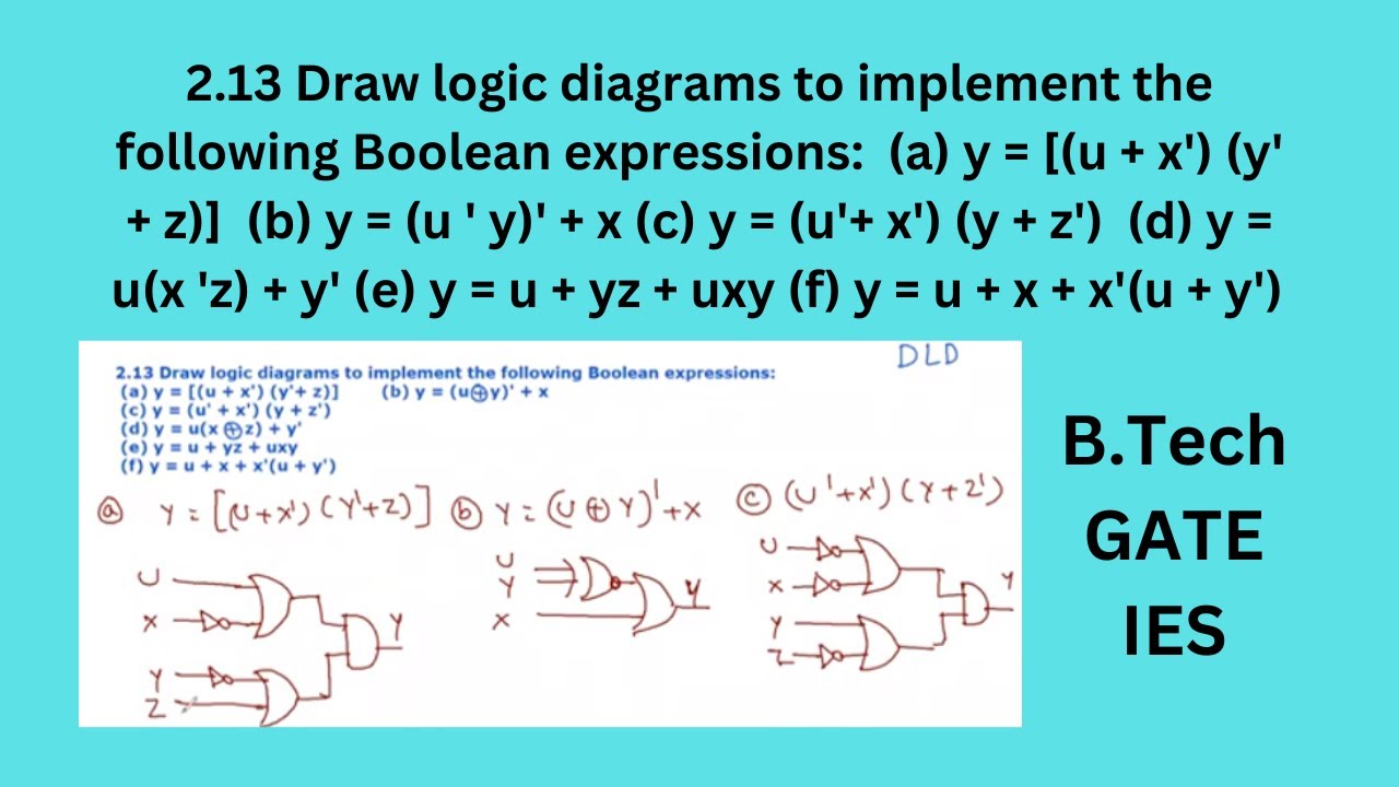
2.13 Draw logic diagram to implement the following Boolean expressions
![[Solved]: Problem 1: Question Consider the two circuit dia](https://i2.wp.com/media.cheggcdn.com/media/b71/b715f4cf-dd24-4d3b-83a8-58563c5645ed/phpfrKPCd)
[Solved]: Problem 1: Question Consider the two circuit dia

2's Complement circuit. Compared to a conventional adder 2's complement
![[DIAGRAM] 2 S Complement Logic Diagram - MYDIAGRAM.ONLINE](https://i2.wp.com/d2vlcm61l7u1fs.cloudfront.net/media/0e8/0e8e409c-cd99-4425-91ed-89dae9a2ec87/phpt8ms0q.png)
[DIAGRAM] 2 S Complement Logic Diagram - MYDIAGRAM.ONLINE

Full Adder And Subtractor Circuit Diagram

Solved Consider the two circuit diagrams below. These two | Chegg.com